


Congestion
Congestion in a network may occur if the load on the network-the number of packets sent to the network-is greater than the capacity of the network-the number of packets a network can handle. Congestion happens in any system that involves waiting.
6.1.1 General Principles of congestion control
Congestion control refers to techniques and mechanisms that can either prevent congestion, before it happens, or remove congestion, after it has happened. In general, we can divide congestion control mechanisms into two broad categories:
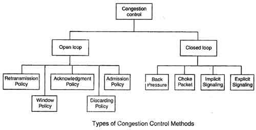

Open-Loop Congestion Control
In open-loop congestion control, policies are applied to prevent congestion before it happens. In these mechanisms, congestion control is handled by either the source or the destination.Major algorithm used are token bucket, leaky bucket.
a) Retransmission Policy
Retransmission in general may increase congestion in the network. However, a good retransmission policy can prevent congestion. The retransmission policy and the retransmission timers must be designed to optimize efficiency and at the same time prevent congestion. For example, the retransmission policy used by TCP (explained later) is designed to prevent or alleviate congestion.
b) Window Policy
The type of window at the sender may also affect congestion. The Selective Repeat window is better than the Go-Back-N window for congestion control. In the Go-Back-N window, when the timer for a packet times out, several packets may be resent, although some may have arrived safe and sound at the receiver. This duplication may make the congestion worse. The Selective Repeat window, on the other hand, tries to send the specific packets that have been lost or corrupted.
c)Acknowledgment Policy
The acknowledgment policy imposed by the receiver may also affect congestion. If the receiver does not acknowledge every packet it receives, it may slow down the sender and help prevent congestion. Several approaches are used in this case. A receiver may send an acknowledgment only if it has a packet to be sent or a special timer expires. A receiver may decide to acknowledge only N packets at a time. We need to know that the acknowledgments are also part of the load in a network. Sending fewer acknowledgments means imposing less load on the network.
d) Discarding Policy
A good discarding policy by the routers may prevent congestion and at the same time may not harm the integrity of the transmission. For example, in audio transmission, if the policy is to discard less sensitive packets when congestion is likely to happen, the quality of sound is still preserved and congestion is prevented or alleviated.
e) Admission Policy
An admission policy, which is a quality-of-service mechanism, can also prevent congestion in virtual-circuit networks. Switches in a flow first check the resource requirement of a flow before admitting it to the network. A router can deny establishing a virtual circuit connection if there is congestion in the network or if there is a possibility of future congestion.
2) Closed-Loop Congestion Control
Closed-loop congestion control mechanisms try to alleviate congestion after it happens.Methods used in close loop are admission control, load shedding, jitter control, fair queuing, weighted fair queuing, choke packet, hop by hop choke packet.Several mechanisms have been used by different protocols.
a) Backpressure
The technique of backpressure refers to a congestion control mechanism in which a congested node stops receiving data from the immediate upstream node or nodes. This may cause the upstream node or nodes to become congested, and they, in turn, reject data from their upstream nodes or nodes. And so on. Backpressure is a node-to-node congestion control that starts with a node and propagates, in the opposite direction of data flow, to the source. The backpressure technique can be applied only to virtual circuit networks, in which each node knows the upstream node from which a flow of data is corning.

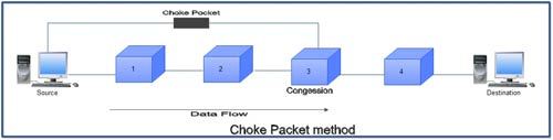
b) Choke Packet
A choke packet is a packet sent by a node to the source to inform it of congestion. In the choke packet method, the warning is from the router, which has encountered congestion, to the source station directly. The intermediate nodes through which the packet has travelled are not warned. We have seen an example of this type of control in ICMP. When a router in the Internet is overwhelmed with IP datagrams, it may discard some of them; but it informs the source host, using a source quench ICMP message. The warning message goes directly to the source station; the intermediate routers, and does not take any action.

c) Implicit Signalling
In implicit signalling, there is no communication between the congested node or nodes and the source. The source guesses that there is a congestion somewhere in the network from other symptoms. For example, when a source sends several packets and there is no acknowledgment for a while, one assumption is that the network is congested. The delay in receiving an acknowledgment is interpreted as congestion in the network; the source should slow down.
d) Explicit Signalling
The node that experiences congestion can explicitly send a signal to the source or destination. The explicit signalling method, however, is different from the choke packet method. In the choke packet method, a separate packet is used for this purpose; in the explicit signalling method, the signal is included in the packets that carry data.
- Backward Signalling: A bit can be set in a packet moving in the direction opposite to the congestion. This bit can warn the source that there is congestion and that it needs to slow down to avoid the discarding of packets.
- Forward Signalling: A bit can be set in a packet moving in the direction of the congestion. This bit can warn the destination that there is congestion. The receiver in this case can use policies, such as slowing down the acknowledgments, to alleviate the congestion.
6.1. 4 Congestion control in Datagram Subnets (UDP)
Congestion control in Datagram Subnets is achieved by sending warning to sender in advance. Each router can easily monitor the utilization of its output lines. If utilization is greater than threshold value then output line may be congested in future so mark it as warning state. Each newly arriving packet is checked to see if its output line is in warning state. If it is, some action is taken. The actions are:
- The warning bit
- Choke packets
- Hop-by-hop choke packet
- Random Early Detection
A) The warning bit
When a new packet is to be transmitted on the output line marked as warning state, a special bit is added in header to signal this state. At the destination, this information is sent back with ACK to the sender so that it could cut the traffic. When warning bit is absent, sender increases its transmitting rate. It uses a whole trip (source – > destination -> source) to tell the source to slow down.
B) Choke Packet Technique
In this approach, the router sends a choke packet back to the source host. The original packet is marked so that it would not generate any more choke packets further along the path and is then forwarded in the usual way. When the source gets the choke packet, it is required to reduce the traffic by X packets. The whole process is illustrated in fig 1.

Figure : Functioning of choke packets, (a) Heavy traffic between nodes P and Q, (b) Node Q sends the Choke packet to P, (c) Choke packet reaches P, (d) P reduces the flow and sends a reduced flow out, (e) Reduced flow reaches node Q
Problem: It does not work well if the choke packet travels a long distance to reach the source because reduction of flow starts from source node rather than intermediate node. This problem can be solved by hop-by-hop approach.
C) Hop-by Hop Choke Packets
In this approach, unlike choke packet, reduction of flow starts from intermediate node rather than source node. To understand this, let us refer the figure 2. When the choke packet reaches the nearest router (say R) from router Q, it reduces the flow. However, router R now requires devoting more buffers to the flow since the source is still sending at full blast but it gives router Q immediate relief. In the next step, the choke packet reaches P and flow genuinely slow down. The net effect of hop-by-hop scheme is to provide quick relief at the point of congestion at the price of using up more buffers upstream.

Figure 2: Functioning of Hop-by-Hop choke packets, (a) Heavy traffic between nodes P and Q, (b) Node Q sends the Choke packet to P, (c) Choke packet reaches R, and the flow between R and Q is decreased, (d) Choke packer reaches P, and P reduces the flow out.
D )Load shedding
When none of the techniques mentioned above are failed to disappear congestion, router can just throw the packets away. In load shedding approach, router just throw packet away. In other words, router starts dropping packets. Now issue is-which packets to discard? Router may pick packets at random to drop or it may depend on the application running. For example, for file transfer, an old packet is important more than a new one and for multimedia application, a new packet is more important than an old one.
E) Random Early Detection
It is based on the well-known saying-prevention is better than cure i.e. drop packets early before congestion occurs. It leads to the idea of discarding packets before all the buffer space is really exhausted. Now question is –When to start discarding? Since the router cannot tell which source is causing most of the trouble, it picks at random from the queue.
How should the router tell the source about problem?
One way is to send it a choke packet. But the problem is that it puts more load on the already congested network. Second way is, just discard the selected packets and not report it. Due to lack of ACK, the source will take action. Since it knows that the lost packets are generally caused by congestion, it will respond by slow down instead of retransmission.
6.4 QOS Concept
- QoScan be defined as the set of parameter that defines the properties of data stream.
- QoSis the ability to provide different priority to different applications, users, or data flows, or to guarantee a certain level of performance to a data flow.
- It Prioritize network traffic, to help ensure that the most important data gets through the network as quickly as possible.
- Primary goal of QoSis to provide priority including dedicated bandwidth, controlled jitter and latency, and also to ensure the minimum loss of datagram.
- In Short, QoScan be defined as the capability of a network to provide better service to selected network traffic over various technology ATM, SONET etc.
6.4 .1 QOS Parameters
a) Delay
The delay of a network is defined as the character that specifies how long it takes for a bit to travel across the network from one node or endpoint to another. Application can tolerate delay in different degrees. Processing delay, Queuing delay, Transmission delay, propagation delay, total round trip delay.
b) Bandwidth
The rate of data transfer, bit rate or throughput, measured in bits per second (bps). Different application need different bandwidth
c) Jitter (1 marks)
It is defined as the variation in the packet delay for packets belonging to the same flow. High jitter means the difference between delays is large and low jitter means the variation is small.
d) Reliability
It is a characteristic that a flow need. Lack if reliability means losing a packet or acknowledgment, which entails retransmission.
6.4 Function of IPQOS & techniques to achieveQos
A) Policing
Policing schemes are used to specify the data rate at which a data stream is allowed to enter a network. Criteria for policing include:
- Average rate, number of packets per time interval at which packets of a data flow can be sent into the network. A key issue is the interval of time over which the average rate will be policed.
- Peak rate, the maximum number of packets that can be sent into the network over a short period of time.
- Burst size, the maximum number of packets that can be sent into the network over an extremely short interval of time.
B )Shaping
Traffic shaping is a mechanism to control the amount and the rate of the traffic sent to the network. Two techniques can shape traffic: leaky bucket and token bucket.
- Leaky Bucket
If a bucket has a small hole at the bottom, the water leaks from the bucket at a constant rate as long as there is water in the bucket. The rate at which the water leaks does not depend on the rate at which the water is input to the bucket unless the bucket is empty. The input rate can vary, but the output rate remains constant. Similarly, in networking, a technique called leaky bucket can smooth out bursty traffic. Bursty chunks are stored in the bucket and sent out at an average rate. Figure below shows a leaky bucket and its effects.
et.
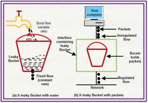
Leaky Bucket Implementation
A FIFO queue holds the packets. If the traffic consists of fixed-size packets (e.g., cells in ATM networks), the process removes a fixed number of packets from the queue at each tick of the clock. If the traffic consists of variable-length packets, the fixed output rate must be based on the number of bytes or bits.
The following is an algorithm for variable-length packets:
- Initialize a counter to n at the tick of the clock.
- If n is greater than the size of the packet, send the packet and decrement the counter by the packet size. Repeat this step until n is smaller than the packet size.
- Reset the counter and go to step 1.
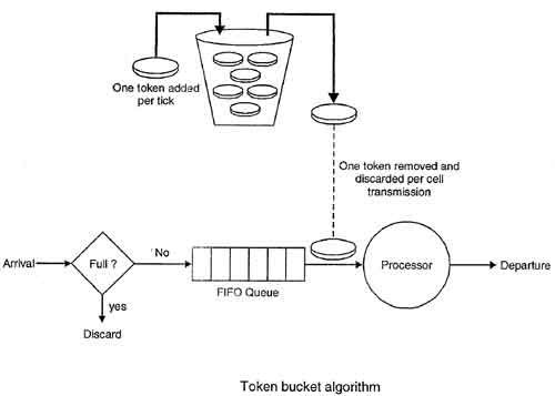
2. Token Bucket
The leaky bucket is very restrictive. It does not credit an idle host. For example, if a host is not sending for a while, its bucket becomes empty. Now if the host has bursty data, the leaky bucket allows only an average rate. The time when the host was idle is not taken into account. On the other hand, the token bucket algorithm allows idle hosts to accumulate credit for the future in the form of tokens. For each tick of the clock, the system sends n tokens to the bucket. The system removes one token for every cell (or byte) of data sent. For example, if n is 100 and the host is idle for 100 ticks, the bucket collects 10,000 tokens. Now the host can consume all these tokens in one tick with 10,000 cells, or the host takes 1000 ticks with 10 cells per tick. In other words, the host can send bursty data as long as the bucket is not empty. Figure below shows the idea. The token bucket can easily be implemented with a counter. The token is initialized to zero. Each time a token is added, the counter is incremented by 1. Each time a unit of data is sent, the counter is decremented by 1. When the counter is zero, the host cannot send data.
mpty.
c) Scheduling
A scheduling mechanism is a scheme for selecting packets for transmission from an output link queue with packets of multiple data streams. Some of the Scheduling algorithm include:
- FIFO
- Priority Queueing
- Weighted Fair Queueing
D) Admission Control
Admission Control is a validation process in communication systems where a check is performed before a connection is established to see if current resources are sufficient for the proposed connection.It determines how bandwidth and latency(amount of time a message takes to traverse a system) are allocated to streams with various requirements.It is implemented between network edges and core to control the traffic entering the network.
Integrated Service
ISDN is the abbreviation of Integrated Services Digital Network which is a set of communications standard for instantaneous digital transmission of data, audio, video, and other services related to network, in excess of the conventional circuits of the community switched telephone network. ISDN (Integrated Services Digital Network) was introduced by CCITT in 1988. ISDN (Integrated Services Digital Network) is a method to transfer voice data with some particular services accessible for data. The major feature of ISDN (Integrated Services Digital Network) is that it put together speech and information on the same line which were not presented in classic telephone system.
The main element of ISDN (Integrated Services Digital Network) services are ability to deliver maximum data within the combination of voice, data, video, fax, over a single line while it provides at least two instantaneous connections. User can attach several devices to the line according to their need instead of purchasing many analog phone lines.
ISDN (Integrated Services Digital Network) make available access to packet switched networks because it is a circuit switched telephone network system. Therefore it provides better quality of voice data than an analog phone. ISDN (Integrated Services Digital Network) also offer 64 kbits/s and in some countries it provides 128 kbites/s in both uploading and downloading. The ISDN-B channel is responsible to provide greater data rate. ISDN (Integrated Services Digital Network) is a best suit of digital services existing on layer 1, layer2, and layer3 of OSI reference model.
ISDN Advantages
- The basic advantage of ISDN is to facilitate the user with multiple digital channels. These channels can operate concurrently through the same one copper wire pair.
- The digital signals broadcasting transversely the telephone lines.
- ISDN provides high data rate because of digital scheme which is 56kbps.
- ISDN network lines are able to switch manifold devices on the single line such as faxes, computers, cash registers credit cards readers, and many other devices. These all devices can work together and directly be connected to a single line.
- ISDN takes only 2 seconds to launch a connection while other modems take 30 to 60 second for establishment.
ISDN Disadvantages
- The disadvantage of ISDN lines is that it is very costly than the other typical telephone system.
- ISDN requires specialized digital devices just like Telephone Company.
Differentiated Service takes a stateless approach that minimizes the need for nodes in the network to remember anything about flows. It is not as good at providing QoS as the stateful approach, but more practical to implement across the Internet. Diff-Serv devices at the edge of the network mark packets in a way that describes the service level they should receive.
In the IntServ/RSVP environment, applications negotiate with the network for service. IntServ is said to be application aware, which allows hosts to communicate useful information to the network about their requirements and the state of their flows. In contrast, Diff-Serv is not application aware (although work is underway to make it so). Since Diff-Serv does not listen to applications, it does not benefit from feedback that applications could provide. Since it doesn’t know exactly what an application needs, it may fail to provide it with an appropriate service level. In addition, Diff-Serv is not in touch with the receiving host, so it doesn’t know whether that host can handle the services it will allocate.