What is the ER Model?
- The ER or (Entity Relational Model) is a high-level conceptual data model diagram. Entity-Relation model is based on the notion of real-world entities and the relationship between them.
- ER modeling helps you to analyze data requirements systematically to produce a well-designed database. So, it is considered a best practice to complete ER modeling before implementing your database.
What is ER Diagrams?
Entity relationship diagram displays the relationships of entity set stored in a database. In other words, we can say that ER diagrams help you to explain the logical structure of databases. At first look, an ER diagram looks very similar to the flowchart. However, ER Diagram includes many specialized symbols, and its meanings make this model unique.
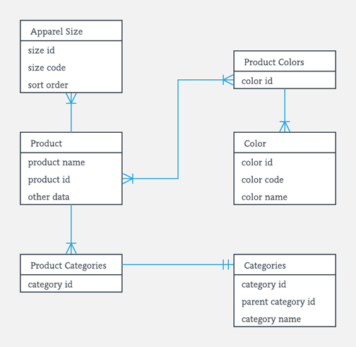
Facts about ER Diagram Model:
- ER model allows you to draw Database Design
- It is an easy to use graphical tool for modeling data
- Widely used in Database Design
- It is a GUI representation of the logical structure of a Database
- It helps you to identifies the entities which exist in a system and the relationships between those entities
Why use ER Diagrams?
Here, are prime reasons for using the ER Diagram
- Helps you to define terms related to entity relationship modeling
- Provide a preview of how all your tables should connect, what fields are going to be on each table
- Helps to describe entities, attributes, relationships
- ER diagrams are translatable into relational tables which allows you to build databases quickly
- ER diagrams can be used by database designers as a blueprint for implementing data in specific software applications
- The database designer gains a better understanding of the information to be contained in the database with the help of ERP diagram
- ERD is allowed you to communicate with the logical structure of the database to users
Components of the ER Diagram
This model is based on three basic concepts:
- Entities
- Attributes
- Relationships
Example
For example, in a University database, we might have entities for Students, Courses, and Lecturers. Students entity can have attributes like Rollno, Name, and DeptID. They might have relationships with Courses and Lecturers.

i .ENTITY
A real-world thing either living or non-living that is easily recognizable and nonrecognizable. It is anything in the enterprise that is to be represented in our database. It may be a physical thing or simply a fact about the enterprise or an event that happens in the real world.
An entity can be place, person, object, event or a concept, which stores data in the database. The characteristics of entities are must have an attribute, and a unique key. Every entity is made up of some ‘attributes’ which represent that entity.
Examples of entities:
- Person: Employee, Student, Patient
- Place: Store, Building
- Object: Machine, product, and Car
- Event: Sale, Registration, Renewal
- Concept: Account, Course
Notation of an Entity
Entity set:
Student
An entity set is a group of similar kind of entities. It may contain entities with attribute sharing similar values. Entities are represented by their properties, which also called attributes. All attributes have their separate values. For example, a student entity may have a name, age, class, as attributes.

Example of Entities:
A university may have some departments. All these departments employ various lecturers and offer several programs.
Some courses make up each program. Students register in a particular program and enroll in various courses. A lecturer from the specific department takes each course, and each lecturer teaches a various group of students.
ii.Relationship
Relationship is nothing but an association among two or more entities. E.g., Tom works in the Chemistry department.

Entities take part in relationships. We can often identify relationships with verbs or verb phrases.
For example:
- You are attending this lecture
- I am giving the lecture
- Just loke entities, we can classify relationships according to relationship-types:
- A student attends a lecture
- A lecturer is giving a lecture.
Weak Entities
A weak entity is a type of entity which doesn’t have its key attribute. It can be identified uniquely by considering the primary key of another entity. For that, weak entity sets need to have participation.

In aboe example, “Trans No” is a discriminator within a group of transactions in an ATM.
Let’s learn more about a weak entity by comparing it with a Strong Entity
| Strong Entity Set | Weak Entity Set |
| Strong entity set always has a primary key. | It does not have enough attributes to build a primary key. |
| It is represented by a rectangle symbol. | It is represented by a double rectangle symbol. |
| It contains a Primary key represented by the underline symbol. | It contains a Partial Key which is represented by a dashed underline symbol. |
| The member of a strong entity set is called as dominant entity set. | The member of a weak entity set called as a subordinate entity set. |
| Primary Key is one of its attributes which helps to identify its member. | In a weak entity set, it is a combination of primary key and partial key of the strong entity set. |
| In the ER diagram the relationship between two strong entity set shown by using a diamond symbol. | The relationship between one strong and a weak entity set shown by using the double diamond symbol. |
| The connecting line of the strong entity set with the relationship is single. | The line connecting the weak entity set for identifying relationship is double. |
iii.Attributes
It is a single-valued property of either an entity-type or a relationship-type. For example, a lecture might have attributes: time, date, duration, place, etc.
An attribute is represented by an Ellipse

i.Simple attributes
Simple attributes are those drawn from the atomic value domains; they are also called single-valued attributes. In the COMPANY database, an example of this would be: Name = {John} ; Age = {23}
ii.Composite Attribute –
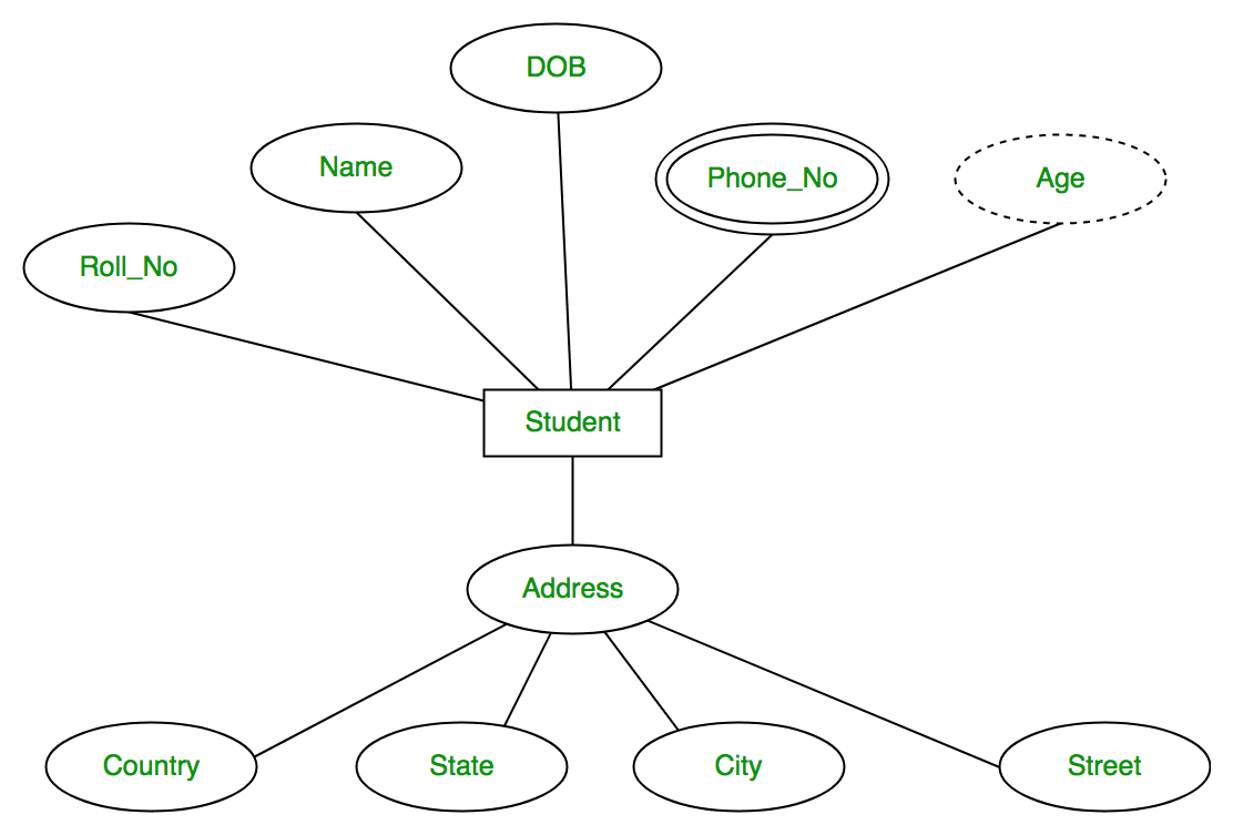
An attribute composed of many other attribute is called as composite attribute. For example, Address attribute of student Entity type consists of Street, City, State, and Country. In ER diagram, composite attribute is represented by an oval comprising of ovals.

iii.Multivalued Attribute –
An attribute consisting more than one value for a given entity. For example, Phone_No (can be more than one for a given student). In ER diagram, multivalued attribute is represented by double oval.

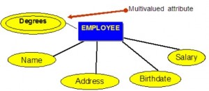
An example of a multivalued attribute from the COMPANY database, as seen in Figure 8.4, are the degrees of an employee: BSc, MIT, PhD.
iv. Derived Attribute –
This type of attribute does not include in the physical database. However, their values are derived from other attributes present in the database. For example, age should not be stored directly. Instead, it should be derived from the DOB of that employee. In ER diagram, derived attribute is represented by dashed oval.

the complete entity type Student with its attributes can be represented as:
Keys
- Keys play an important role in the relational database.
- It is used to uniquely identify any record or row of data from the table. It is also used to establish and identify relationships between tables.
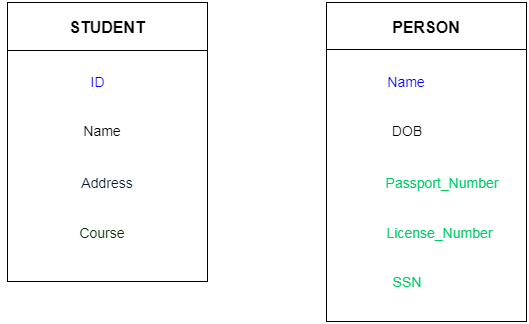
For example: In Student table, ID is used as a key because it is unique for each student. In PERSON table, passport_number, license_number, SSN are keys since they are unique for each person.
Types of key:

1. Primary key
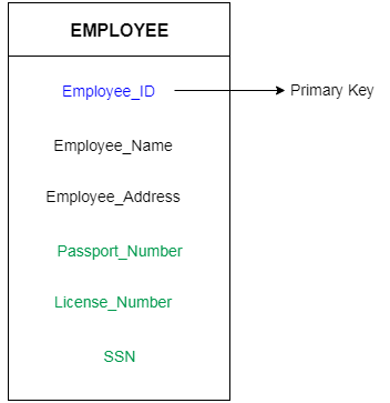
- It is the first key which is used to identify one and only one instance of an entity uniquely. An entity can contain multiple keys as we saw in PERSON table. The key which is most suitable from those lists become a primary key.
- In the EMPLOYEE table, ID can be primary key since it is unique for each employee. In the EMPLOYEE table, we can even select License_Number and Passport_Number as primary key since they are also unique.
- For each entity, selection of the primary key is based on requirement and developers.
2. Candidate key
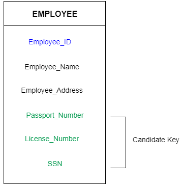
- A candidate key is an attribute or set of an attribute which can uniquely identify a tuple.
- The remaining attributes except for primary key are considered as a candidate key. The candidate keys are as strong as the primary key.
For example: In the EMPLOYEE table, id is best suited for the primary key. Rest of the attributes like SSN, Passport_Number, and License_Number, etc. are considered as a candidate key.
3. Super Key
Super key is a set of an attribute which can uniquely identify a tuple. Super key is a superset of a candidate key.
For example: In the above EMPLOYEE table, for(EMPLOEE_ID, EMPLOYEE_NAME) the name of two employees can be the same, but their EMPLYEE_ID can’t be the same. Hence, this combination can also be a key.
The super key would be EMPLOYEE-ID, (EMPLOYEE_ID, EMPLOYEE-NAME), etc.
4. Foreign key
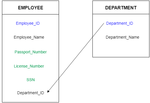
- Foreign keys are the column of the table which is used to point to the primary key of another table.
- In a company, every employee works in a specific department, and employee and department are two different entities. So we can’t store the information of the department in the employee table. That’s why we link these two tables through the primary key of one table.
- We add the primary key of the DEPARTMENT table, Department_Id as a new attribute in the EMPLOYEE table.
- Now in the EMPLOYEE table, Department_Id is the foreign key, and both the tables are related.
Generalization
- Generalization is like a bottom-up approach in which two or more entities of lower level combine to form a higher level entity if they have some attributes in common.
- In generalization, an entity of a higher level can also combine with the entities of the lower level to form a further higher level entity.
- Generalization is more like subclass and superclass system, but the only difference is the approach. Generalization uses the bottom-up approach.
- In generalization, entities are combined to form a more generalized entity, i.e., subclasses are combined to make a superclass.
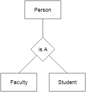
For example, Faculty and Student entities can be generalized and create a higher level entity Person.
Specialization
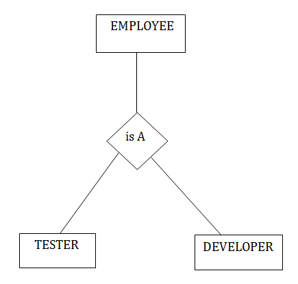
- Specialization is a top-down approach, and it is opposite to Generalization. In specialization, one higher level entity can be broken down into two lower level entities.
- Specialization is used to identify the subset of an entity set that shares some distinguishing characteristics.
- Normally, the superclass is defined first, the subclass and its related attributes are defined next, and relationship set are then added.
For example: In an Employee management system, EMPLOYEE entity can be specialized as TESTER or DEVELOPER based on what role they play in the company.
Aggregation
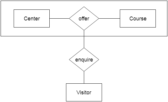
In aggregation, the relation between two entities is treated as a single entity. In aggregation, relationship with its corresponding entities is aggregated into a higher level entity.
For example: Center entity offers the Course entity act as a single entity in the relationship which is in a relationship with another entity visitor. In the real world, if a visitor visits a coaching center then he will never enquiry about the Course only or just about the Center instead he will ask the enquiry about both.
Mapping constraints/Cardinality
The number of times an entity of an entity set participates in a relationship set is known as cardinality. Cardinality can be of different types:
- One-to-One Relationships
- One -to-Many Relationships
- May to One Relationships
- Many-to-Many Relationships
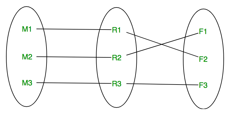
1.One to one (1:1)– A one to one (1:1) relationship is the relationship of one entity to only one other entity, and vice versa. It should be rare in any relational database design. In fact, it could indicate that two entities actually belong in the same table.An example from the COMPANY database is one employee is associated with one spouse, and one spouse is associated with one employee.
Let us assume that a male can marry to one female and a female can marry to one male. So the relationship will be one to one.

Using Sets, it can be represented as:
One to many (1:M) relationship
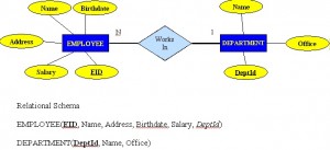
A one to many (1:M) relationship should be the norm in any relational database design and is found in all relational database environments. For example, one department has many employees. Figure 8.7 shows the relationship of one of these employees to the department.
2. Many to one – When entities in one entity set can take part only once in the relationship set and entities in other entity set can take part more than once in the relationship set, cardinality is many to one. Let us assume that a student can take only one course but one course can be taken by many students. So the cardinality will be n to 1. It means that for one course there can be n students but for one student, there will be only one course.
 Using Sets, it can be represented as:
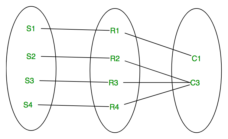
In this case, each student is taking only 1 course but 1 course has been taken by many students.
3.Many to many (M:N)– When entities in all entity sets can take part more than once in the relationship cardinality is many to many. Let us assume that a student can take more than one course and one course can be taken by many students. So the relationship will be many to many.

Using sets, it can be represented as:
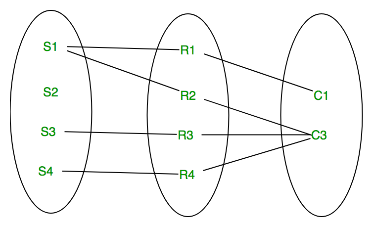
In this example, student S1 is enrolled in C1 and C3 and Course C3 is enrolled by S1, S3 and S4. So it is many to many relationships.
For a many to many relationship, consider the following points:
- It cannot be implemented as such in the relational model.
- It can be changed into two 1:M relationships.
- It can be implemented by breaking up to produce a set of 1:M relationships.
- It involves the implementation of a composite entity.
- Creates two or more 1:M relationships.
- The composite entity table must contain at least the primary keys of the original tables.
- The linking table contains multiple occurrences of the foreign key values.
- Additional attributes may be assigned as needed.
- It can avoid problems inherent in an M:N relationship by creating a composite entity or bridge entity. For example, an employee can work on many projects OR a project can have many employees working on it, depending on the business rules. Or, a student can have many classes and a class can hold many students.
Figure shows another another aspect of the M:N relationship where an employee has different start dates for different projects. Therefore, we need a JOIN table that contains the EID, Code and StartDate.
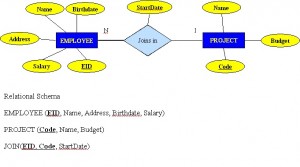
Example of mapping an M:N binary relationship type
- For each M:N binary relationship, identify two relations.
- A and B represent two entity types participating in R.
- Create a new relation S to represent R.
- S needs to contain the PKs of A and B. These together can be the PK in the S table OR these together with another simple attribute in the new table R can be the PK.
- The combination of the primary keys (A and B) will make the primary key of S.
nary relationship (recursive)
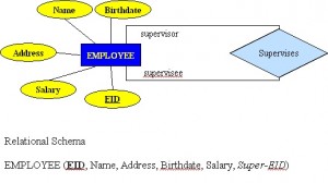
A unary relationship, also called recursive, is one in which a relationship exists between occurrences of the same entity set. In this relationship, the primary and foreign keys are the same, but they represent two entities with different roles. See Figure 8.9 for an example.
For some entities in a unary relationship, a separate column can be created that refers to the primary key of the same entity set.
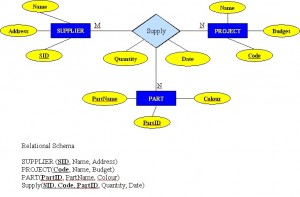
Ternary Relationships
A ternary relationship is a relationship type that involves many to many relationships between three tables.
Refer to Figure 8.10 for an example of mapping a ternary relationship type. Note n-ary means multiple tables in a relationship. (Remember, N = many.)
- For each n-ary (> 2) relationship, create a new relation to represent the relationship.
- The primary key of the new relation is a combination of the primary keys of the participating entities that hold the N (many) side.
- In most cases of an n-ary relationship, all the participating entities hold a many side.
ER- Diagram Notations
ER- Diagram is a visual representation of data that describe how data is related to each other.
- Rectangles: This symbol represent entity types
- Ellipses : Symbol represent attributes
- Diamonds: This symbol represents relationship types
- Lines: It links attributes to entity types and entity types with other relationship types
- Primary key: attributes are underlined
- Double Ellipses: Represent multi-valued attributes

